AS/NZS 3008.1.1:2025 · AUSTRALIAN CONDITIONS
Cable sizing
Set the conditions. Find the right size.
SELECTED CABLE
Ready to calculate
Corrected current capacity · Iz
Enter your conditions
Rating & correction factors
Pass means the checks shown pass within this tool’s scope. It is not approval of a complete installation. Verify earthing, fault-loop disconnection, equipment limits and all application-specific requirements.
Request a cable quote ↗Compare sizes
Current capacity + voltage + selected checks| Size | Capacity Iz | Voltage change | Result |
|---|
COMPLETE YOUR PROJECT
Find your cable.
 JOCA solar DC cable ↗
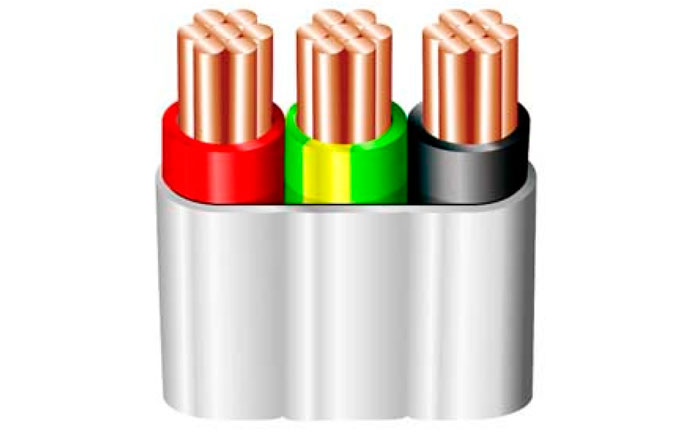 AC cables & wiring ↗
Scope, standard references & assumptions
Calculation data: AS/NZS 3008.1.1:2025, typical Australian conditions. This tool supports 1–300 mm² copper and 16–300 mm² aluminium, 75°C thermoplastic and 90°C cross-linked installation cables, single-phase AC, balanced three-phase AC and two-conductor DC. Flexible and tinned options support copper only. It uses separate AC/DC current-rating tables and tabulated R/X at the selected maximum design temperature.
Current capacity follows Clause 2.3.1: the applicable base rating multiplied by supported installation/grouping, ambient temperature, depth and soil factors. Table and column references appear with each result. Grouped cables are assumed to have uniform thermal grade and equal loading. Tray calculations require a single layer per tier and at least 300 mm between horizontal tiers. Underground calculations support one row, one circuit per PVC duct; grouped underground circuits require the reference 0.5 m depth and 1.2°C·m/W soil. Other combinations are blocked instead of extrapolated.
Voltage calculations follow Clauses 4.3 and 4.5 with resistance from Tables 4.5–4.8 or 4.10–4.11, and reactance from Tables 4.1–4.2. Worst-case AC uses √(R² + X²); specified lagging PF uses R·PF + X·√(1−PF²). Multiply by 2·I·L/1000 for single-phase/DC or √3·I·L/1000 for balanced three-phase. DC reactance is zero. Single cores within each circuit touch; spacing controls the clearance between circuit groups, not between phase conductors. Rise is the magnitude for reverse power flow under the selected PF model.
Optional active-conductor fault withstand uses I²t ≤ K²S² (Clause 5.3, Tables 5.1 and 5.2), with initial temperature 75°C or 90°C and final temperature 160°C or 250°C respectively. The complete protection coordination, earth conductor, neutral sizing, disconnection time and device let-through checks are not automated. Significant harmonics, unbalanced circuits, parallel conductors, shaped conductors, armoured/MIMS/aerial cables, leading PF and non-standard thermal conditions are outside scope.
AS/NZS 3000 and application-specific standards still apply. This calculator does not determine PV string design current under AS/NZS 5033, battery system compliance under AS/NZS 5139, generator compliance under AS/NZS 3010, or inverter compliance under AS/NZS 4777. Manufacturer cable and termination ratings can impose lower limits. Confirm final selection with a licensed electrical professional.